CS 21 25.2 Laboratory Exercise 7
Pipelined Processor
Overview
You will be using Logisim to modify an existing pipelined RISC-V processor implementation to support additional functionalities.
General Instructions
For this laboratory activity, you are to work on one HOPELEx Checkpoint Item that will aid in your understanding of the RISC-V pipelined processor.
At the end of the HOPELEx Checkpoints are take-home exercises called TakeHOPE items. These are not graded and will not be submitted, but will help you prepare for the HOPE.
Relevant Links
- Ripes Fork: https://ripes.upd-dcs.work
- Google Classroom (slides, submission bin): https://classroom.google.com/u/2/c/ODQwNDkwODYxODg3
- RISC-V Green Card: https://drive.google.com/file/d/1xSll1ON5cSaOQhoGxpkvr4fKe7lGQFy3/view
- Lab 7 Logisim Template: https://drive.google.com/file/d/1ACOcglAVt0fAhkqTXbGcZcPN1bg8Xmi4/view?usp=sharing
Logisim Template
Overview
A Logisim-Evolution template for a working RISC-V pipelined processor can be downloaded via the link in the previous section. This processor implementation supports the following instructions:
lwswaddsubandorsltaddibeqjal
Recommended zoom level
The given template is meant to be viewed at a zoom level of x0.9.
The bottom part of the template consists of the pipelined datapath and control while the top part provides a view of important values arranged by pipeline stage.
Basic execution
Before moving forward, select Simulate > Reset Simulation (or hit Ctrl/Cmd-r) to restart the simulation state.
Observe that PC4F (i.e., the PC + 4 value in the Fetch stage) is currently at 0x4 and that NextPC is also at 0x4. Ensure you are able to follow how the implementation is able to compute this.
Notice as well that PC4D, PC4E, PC4M, and PC4W are currently at 0x0.
Select Simulate > Manual Tick Half Cycle twice or Simulate > Manual Tick Full Cycle once (preferably using their keyboard shortcuts) to cause the next triggering edge to occur. Notice that the 0x4 value of PC4F has now moved to PC4E, and that PC4F is now 0x8.
Tick the clock once more to see the said values move one stage. Before moving forward, ensure that PC4F is 0xc, PC4D is 0x8, and PC4E is 0x4.
Manual hazard resolution
The template does not have any forwarding or hazard resolution implemented. To perform manual hazard resolution, the top-left corner of the template provides input pins for StallF, StallD, FlushD, and FlushE that can be manually set with the Poke tool.
Use the Poke tool to set StallF to 1, then tick the clock. Verify that PC4F is still 0xc, but PC4D is also 0xc. Ensure you understand why that is the case before proceeding.
Set StallF to 0, then tick the clock once; PC4F should now be 0x10 while PC4D should be 0xc. Then, set both StallF and FlushD to 1. Verify that PC4F and PC4D are unaffected, then tick the clock. What happened to PC4F and PC4D?
Set both StallF and FlushD to 0, then tick the clock thrice; PC4F should now be 0x1c while PC4D should be 0x18. Verify as well that PC4E is 0x14 and PC4M is 0x10.
Finally, think about what setting StallF, StallD, and FlushE to 1 would do, then verify your hypothesis by setting them to 1, ticking the clock, and checking the values of PC4F, PC4D, PC4E, PC4M, and PC4W.
HOPELEx Checkpoint
Checkpoint Task: Forwarding + Hazard Unit
Modify the given Logisim circuit such that:
- A subcircuit named
hazardunitthat detects and resolves hazards is present hazardunitis placed in themaincircuit to serve as its hazard unit- The datapath accommodates forwarding as discussed in class
For your convenience, the complete hazard unit logic is as follows:
| Output | Logic |
|---|---|
ForwardAE = 10 (priority) |
(Rs1E == RdM) & RegWriteM & (Rs1E != 0) |
ForwardAE = 01 |
(Rs1E == RdW) & RegWriteW & (Rs1E != 0) |
ForwardAE = 00 |
Otherwise |
ForwardBE = 10 (priority) |
(Rs2E == RdM) & RegWriteM & (Rs2E != 0) |
ForwardBE = 01 |
(Rs2E == RdW) & RegWriteW & (Rs2E != 0) |
ForwardBE = 00 |
Otherwise |
lwStall (not used outside the hazard unit) |
ResultSrcE_0 & ((Rs1D == RdE ) | (Rs2D == RdE)) |
StallF |
lwStall |
StallD |
lwStall |
FlushD |
PCSrcE |
FlushE |
lwStall | PCSrcE |
Flushing behavior implication
Note that the way FlushD and FlushE are computed implies that the processor employs static branch prediction with a branch-not-taken default.
The complete datapath forwarding logic is as follows:
| Control signal | Effect |
|---|---|
ForwardAE == 00 |
RD1E is first ALU operand |
ForwardAE == 01 |
ResultW is first ALU operand |
ForwardAE == 10 |
ALUResultM is first ALU operand |
ForwardBE == 00 |
RD2E is both WriteDataE value and port 0 input of ALUSrcE multiplexer |
ForwardBE == 01 |
ResultW is both WriteDataE value port 0 input of ALUSrcE multiplexer |
ForwardBE == 10 |
ALUResultM is both WriteDataE value port 0 input of ALUSrcE multiplexer |
The complete pipelined processor diagram may be found below for your convenience:
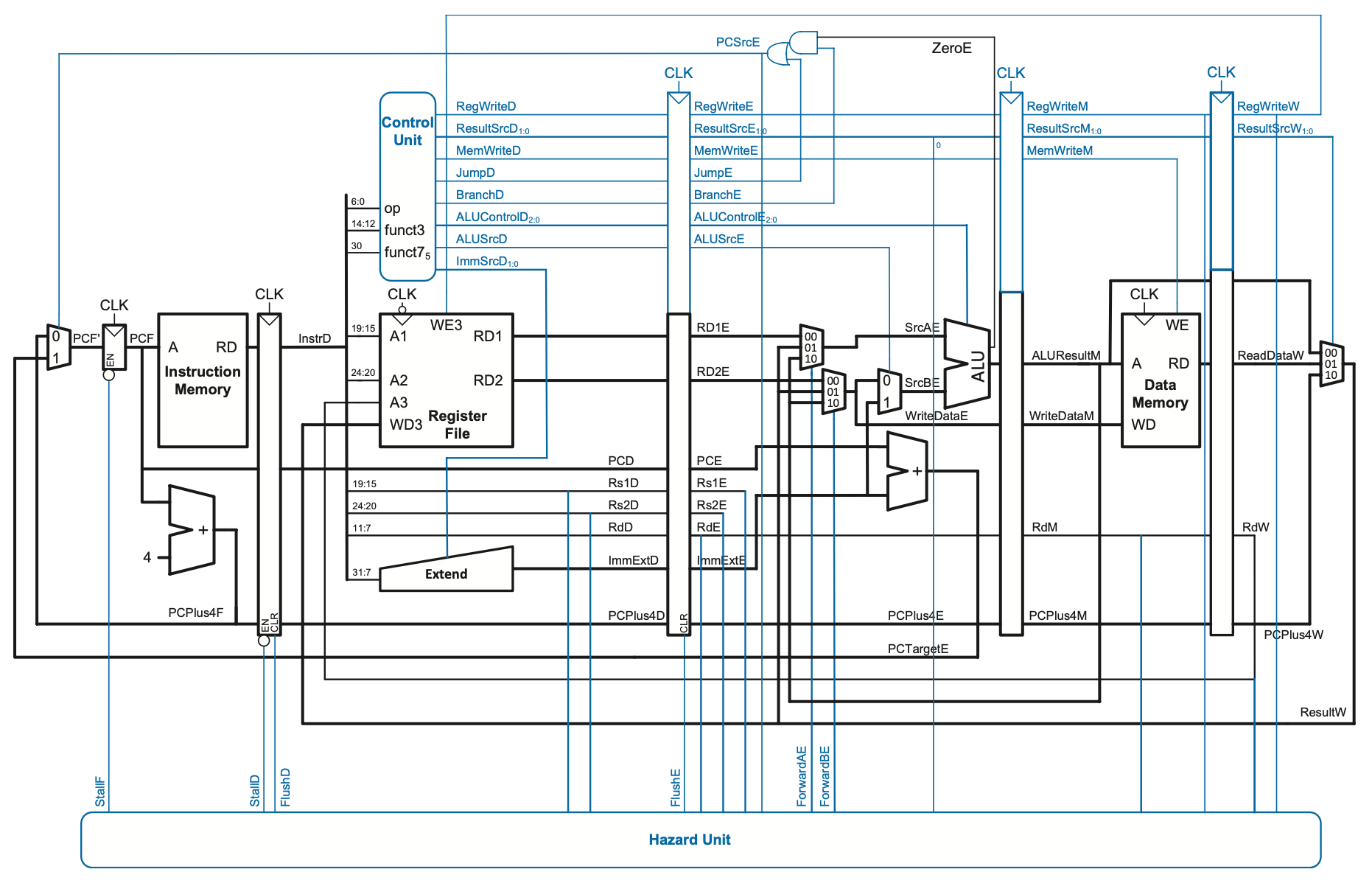
Ensure that:
- All other instructions that were supported before by the template still work as intended
- The input pins for
StallF,StallD,FlushD, andFlushEin the top-right corner of themaincircuit are deleted
You are encouraged to use tunnels and comparators.
Save the resulting circuit as lab07.circ.
Hint: Priority encoders
You may find priority encoders more useful in deriving an implementation of a conditional statement over a implementing with a truth table.
Demo program
Tip: Quick conversion shell script
Supposing the output of the Ripes assembly is in assembly.txt, the following command automatically transforms the said output into its Logisim-ready form in logisim.txt:
You may test your work using the following RISC-V program and compare the resulting register values in the State tab after 37 clock cycles with those of Ripes:
main:
    addi s0, zero, 100    # s0 = 100

    addi t0, zero, 5      # t0 = 5
    addi t1, zero, 10     # t1 = 10
    add  t2, t0, t1       # t2 = 15
    add  t3, t2, t0       # t3 = 20 (forwarding)

    addi t4, zero, 7      # t4 = 7
    sw   t4, 0(s0)        # MEM[100] = 7
    lw   t5, 0(s0)        # t5 = 7
    addi t6, zero, 3
    add  t1, t5, t6       # t1 = 10 (forwarding)

    lw   t2, 0(s0)        # t2 = 7
    add  t3, t2, t0       # t3 = 12 (load-use stall)

    addi t0, zero, 1      # t0 = 1
    addi t1, zero, 2      # t1 = 2
    beq  t0, t1, skip1    # Not taken (forwarding; should not flush)

    addi t2, zero, 99     # t2 = 99

skip1:
    addi t0, zero, 3      # t0 = 3
    addi t1, zero, 3      # t1 = 3
    beq  t0, t1, taken1   # Taken (forwarding; should flush)

    addi t2, zero, 111    # Should be flushed

taken1:
    jal  t0, func         # t0 = PC + 4 (initial fetch should be flushed)
    addi t3, zero, 222    # Should be flushed

after:
    beq  zero, zero, end  # Taken (should not trigger forwarding)

func:
    addi t4, zero, 42     # t4 = 42
    jal  zero, after      # return (no ra needed)

end:
    beq zero, zero, end   # Infinite loop
TakeHOPE Problems
Item 1: 1-bit dynamic branch predictor
Create a 1-bit dynamic branch predictor with a branch-taken default.
Ensure that at least instruction addresses 0x0 to 0x78 have their own entry in the branch history table. You may use an 8-bit RAM component in Logisim for this.
Item 2: 2-bit dynamic branch predictor
Create a 2-bit dynamic branch predictor with a weakly branch-not-taken default.
Ensure that at least instruction addresses 0x0 to 0x78 have their own entry in the branch history table. You may use an 8-bit RAM component in Logisim for this.